Difference between revisions of "Measurement Computing PCI DIO24"
From Rivendell Wiki
(Created page with "MC PCI-DIO24Rivendell has the ability to interface with a wide variety of GPIO cards/devices so that you can react to outside input or...") |
(No difference)
|
Latest revision as of 15:42, 13 March 2018
Rivendell has the ability to interface with a wide variety of GPIO cards/devices so that you can react to outside input or even send an output to switch external devices.
Although Rivendell itself will operate the PCI-DIO24, the drivers do not appear to be available for Linux kernels newer than 2.X
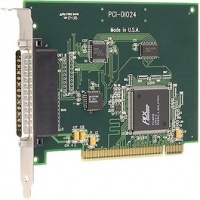
There are a number of built in devices which Rivendell supports out of the box (link to list of devices?), one of which is the Measurement Computing PCI-DIO24[1].
This is a relatively inexpensive way of getting a card with 24 GPIOs.
There are many other devices that may work with Rivendell however you need to have the C code handy so that you can write an interface for the card that is compatible with the way that Rivendell works. You can also consider much cheaper alternatives such as retrofitting USB joysticks/game pads or even a good old Serial connection.
Using the MC PCI DIO 24 with Rivendell
As is always the way, there are a few gotchas with this card. The first of which is that at the point of sale you can specify whether you want Pull Up or Pull Down resistors added to the card. Unfortunately I've checked a few retailers and very few offer this option (and if they do its for a lot more than the original price of the card).
The reason this is important, is if you are expecting to use this card as an input to Rivendell you will have problems for example, pressing a button on a broadcast desk/lifting a fader = song starts to play.
In theory this sounds fine, the card has inputs, you press a button to give it a signal and away it goes. In reality without these pull up/down resistors the pins can be in all sorts of states of varying current/voltage (most likely through interference). This really begins to bite when you wire everything up and Rivendell starts flashing and playing songs left right and centre.
So it would be an idea to solve this. Here you have a couple of options:
- Buy 3 x 2.2K ohm SIP packages (each package has 8 resistors so buy less if you only want to use 8 or 16 inputs) and solder them directly to the board.
- Buy the above but make a small prototype board and wire them to the relevant pins
- Buy 24 (or as many as you need) 2.2K ohm resistors using the same prototype board as above.
I didn't fancy the idea of soldering directly to a board which I could break in an unfortunate soldering iron accident. I also happened to have lots of resistors handy so I opted for the 3rd option of the above. Please note that the SIP packages are a viable option and will cut down on the circuit board size/complexity.
Building the Resistor Circuits
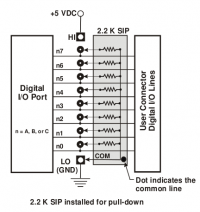
The Rivendell GPIO driver for this card expects 0V to be logic off and 5V for logic on. So we need to build a pull down resistor circuit as per the user manual we're going to be recreating this schematic (please note schematic assumes SIP packages):
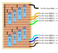
I recreated this using a standard strip board setup, a bunch of resistors, some old network cable (CAT5) and a few lengths of thin black wire I had lying around. Here is the strip board diagram you need to follow (unfortunately it will never look this neat in real life once you've burnt yourself with the soldering iron a few times)
You'll need one of these boards for each set of 8 inputs you want to use. As you hopefully can see by using CAT5 you get a nice colour coded effect going on so theres no need to buy lengths of multi-coloured wire (hence cheaper).
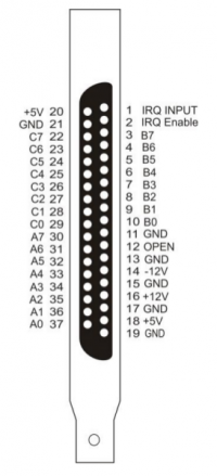
The Measurement computing PCI-DIO24 uses a standard DB37 cable for its pin out connector. You can pick one of these up fairly easily for under £5 if you shop around. To make things easier, I then connected this to a DB37 break out board [2] so that you get nice screw terminals to connect wires to.
Following the pin out guide, I then connected my boards up to the relevant pins (30 - 37 for Input A, 3 - 10 for B and 22 - 29 for C). Any of the ground pins can be used but just in case I connected each board to a dedicated ground pin (you could also simply put an earth terminal on the boards and ground it to that if you wanted to keep the separation from the GPIO cards just in case).
Testing the setup
With everything plugged in, load up gpitest. If you have grounded everything, you should see no inputs have fired up. Now take a length of wire and use Pin 20 +5V (or Pin 18 which is the same) and create a connection to each Input in turn e.g. Pin 37 A0 to make sure your inputs are firing as you expect.
Rivendell works as A0 being IO 1 up to C7 being IO 24.
If you got this far and everything works, wire up your broadcast desks (mini switches or whatever) and away you go.
Remember to add the macros you want to the GPIO setup page for the host machine or nothing will happen. I found it useful to create a bunch of label macros (LB hello from GPIO 1!) and use those to check each input was working properly.


